04.04.2023
For many years, Wind Tunnel tests have been among the most important decision-making aids in solving complicated aerodynamic tasks.
Originally, they were developed for applications in aircraft and vehicle aerodynamics. The wind flow, which is fed e.g. to Formula 1 vehicle models, can be described as very smooth and low in turbulence. In contrast, Wind Tunnels, which are used for structural investigations, are based on a lifelike simulation of the rough and turbulent wind flow.
simulation of the rough and turbulent atmospheric wind. In the course of many years of research in the field of building aerodynamics, a special type of wind tunnel was
a special type of Wind Tunnel, the so-called boundary layer wind tunnel, has been developed. Here, specific internals control the wind tunnel flow in such a way that the
in such a way that the 'laboratory wind' for the model test is reproduced to scale of the storms in nature. Typical buildings investigated in a boundary layer wind tunnel are large structures such as soccer stadiums, bridges, telecommunications towers, high-rise buildings or cooling towers. The object of investigation can be, for example, the determination of the wind load, or also tests on the
vibration susceptibility or wind comfort.
The research group Wind Engineering and Fluid Mechanics (WISt) represents at the faculty the teaching and research in structural aerodynamics, in the related fields of dynamics of structures - in particular wind excited random vibrations - and probabilistic safety theory as well as in fluid mechanics in civil engineering. It evolved from the Working Group on Aerodynamics in Civil Engineering, which was active in these research areas from 1974 to 2001. WISt operates the boundary layer wind tunnel of the Institute of Structural Engineering of the Ruhr-University Bochum, which was built in 1977 under the leadership of the then owner of the working group, Prof. Dr.-Ing. H.-J. Niemann, and has been successfully maintained and expanded since then, see Fig. 1. The wind tunnel was located in building IA on level 0 until March of this year and was the last user of the building. Now the boundary layer wind tunnel has been moved to a new location. Already in November last year, the operation of the boundary layer wind tunnel was temporarily stopped for the purpose of relocation preparations. The relocation work began with the dismantling of the data lines, piezoelectric pressure and hot-wire velocity measurement systems, as well as the optical measurement systems, tracer gas equipment, bridge test stand, all data conditioning and data acquisition. The test preparation workshop, material storage and model archive were also packed.
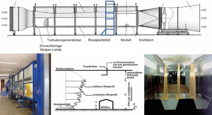
Fig. 1: Boundary layer wind tunnel in Building IA before relocation
Since May 2013, the rooms of the new site have been prepared and equipped with three-phase systems as well as
ventilation systems. A suitable, elongated wind tunnel hall and several ancillary
ancillary rooms have been prepared, a larger one for a model workshop. This also includes a specially
ventilated storage for tracer and cleaning gases. The local situation is very suitable for the
continued operation of the boundary layer wind tunnel. The premises are located directly above the aerodynamic wind tunnel, which was acquired and built by Professor Klaus Gersten, Faculty of Mechanical Engineering. This is a Wind Tunnel with a closed measuring section and return flow, i.e. a wind tunnel of Göttingen design. It was used in research projects for the investigation of vortex systems on delta wings. It is intended to use both Wind Tunnels together for research and industrial investigations.
industrial investigations.
During the 10th and 11th weeks, the large-scale research instrument itself moved to its new location in the
IBN experimental hall to the top floor. The relocation was carried out by a specialized company. Due to the size of the device - or rather the individual parts that could not be
individual parts - a facade segment of the IA building had to be opened. Through the opened
façade, the dismantled parts of the Wind Tunnel could be moved to a larger external area and picked up there by a heavy-duty crane (Figs. 2 and 3).
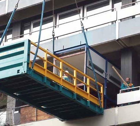
Fig. 2: Picking up a segment of the closed run-up section from the opened facade of building IA.
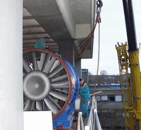
Fig. 3: Photo of the rotor with rotor case and substructure frame from floor 0 of building IA.
All individual parts were lifted onto low-loaders by a heavy-duty crane (Fig. 4) and transported to the open area behind the test halls. The parts were again brought into the IBN building with the aid of the heavy-duty crane through an open roof segment (Figs. 5 and 6).
Assembly has now been completed. Fine-tuning work is currently being performed and the
and the drive motor together with the drive belts and the rotor axis are being realigned. Trial runs will begin shortly in preparation for the resumption of wind tunnel operations.
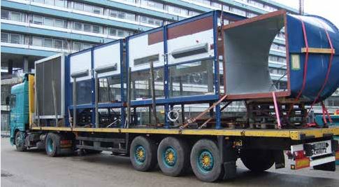
Fig. 4: Transport of the separated main segments including contraction nozzle and diffuser to the open area north of the ICN building.
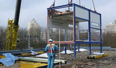
Fig. 5: A main segment of the run-up section in front of the opening in the roof of building ICN.
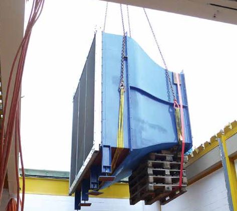
Fig. 6: Swinging in of the contraction nozzle through the opened roof of building ICN.
This text appeared in Newsletter 2014-1. The entire newsletter can be downloaded from the Faculty of Civil and Environmental Engineering website. To the website of the Faculty of Civil and Environmental Engineering.